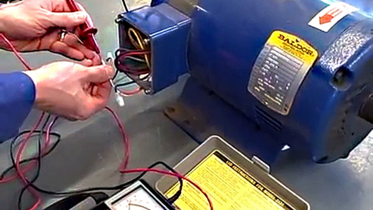
The continuity test can be made in 2 or 4 wires according to the resistance to be measured.
Insulation resistance test procedure for cables.
For cables above 300 volt to 600 volt use 1000 volt megger.
Deviations from the baseline information permit evaluation of the insulation.
Insulation resistance decreases in temperature or moisture.
Perform insulation resistance test on each conductor with respect to ground and adjacent conductors.
Also acceptable values of insulation resistance depend upon the equipment you re testing.
Insulation resistance testing is a non destructive test procedure.
Procedure for cable insulation test.
The insulation resistance test consists in measuring the insulation resistance of a.
The insulation resistance test is the second test required by the electrical safety testing standards.
It is commonly used in the industry for acceptance testing prior to energizing the cable and for maintenance testing programs.
Applied potential shall be 500 volts dc for 300 volt rated cable and 1000 volts dc.
The international electrical testing association neta specification maintenance testing specifications for electrical power distribution equipment and systems provides much more realistic and useful values.
For cables 300 volt use 500 vdc megger.
The megger insulation tester is a small portable instrument that gives you a direct reading of insulation resistance in ohms or megohms.
Developed early in the 20th century the insulation resistance ir test is the oldest and most widely used test for assessing the quality of insulation.
Insulation resistance testing purpose.
Insulation resistance tests should be performed more frequently for systems that show deterioration of insulation material.
2 wires for resistances 1 ω and 4 wires for resistances 1 ω.
Since 80 of electrical maintenance and testing.
Dc hipot testing measures the insulation resistance of cables by applying high voltage and measuring leakage current and the resistance is calculated using ohm s law.
When performing insulation tests on conductors and cable apply the following procedure.
The continuity test also called low resistance measurement is measuring the low resistance of cables from 1 mω to 250 ω.
The test measures the insu lation resistance between the phases and or between phase and ground.
The test voltage values for dc hi pot tests are based upon final factory test voltage which is determined by the type and thickness of insulation the size of conductors the construction of cable and applicable industry.
For cables above and less than 1200 volt use 2500 volt megger.
Hands down without a doubt one of the most universally searched topics on ec m s website from a historical perspective is insulation resistance testing as a result some of our most popular evergreen articles like understanding insulation resistance testing continue to top the charts when it comes to most popular content.
Test results are dependent on the temperature of the insulating material and the humidity of the surrounding environment at the time of the test.
Table 100 22 minimum radii for power cable.
Historically many field electricians use the somewhat arbitrary standard of 1 megohm per kv.

